Introduction
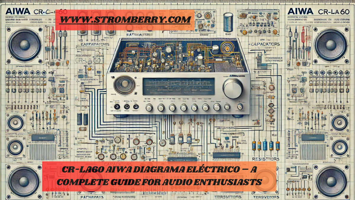
Understanding the CR-LA60 Aiwa diagrama eléctrico is essential for anyone interested in the inner workings of audio systems. This detailed diagram acts as a visual map for the circuits, pathways, and components that power the audio experience in Aiwa’s CR-LA60 model.
The CR-LA60 Aiwa diagrama eléctrico shows detailed internal electrical connections, mapping circuits and components essential for precise audio performance and troubleshooting.
In this guide, we’ll explore the components and electrical connections within the Aiwa CR-LA60 in a way that is easy to understand, highlighting each part’s role and helping you troubleshoot, repair, or enhance this classic device.
1. What Is the CR-LA60 Aiwa Diagrama Eléctrico?
The CR-LA60 Aiwa diagrama eléctrico is a comprehensive electrical schematic for the Aiwa CR-LA60 audio system. This diagram provides a visual representation of how each component is wired, allowing users to understand the entire setup from power input to sound output. It’s more than just a wiring diagram; it’s a functional map that shows each connection’s purpose within the circuit.
2. Why You Need the CR-LA60 Aiwa Diagrama Eléctrico
If you own an Aiwa CR-LA60, the diagrama eléctrico is invaluable for:
- Troubleshooting: Identify and locate faults by visually tracing pathways.
- Repairing: Allows for specific component isolation, making repairs more efficient.
- Understanding Functionality: Learn how different parts work together to produce sound.
- Modifying or Upgrading: Enables customized modifications for enhanced audio performance.
The diagram enables enthusiasts and technicians alike to understand each component’s role, from transistors and resistors to capacitors and transformers.
3. Key Components in the CR-LA60 Electrical Diagram
Each part in the CR-LA60 Aiwa diagrama eléctrico has a unique function. Here’s a breakdown of key components you’ll find:
- Power Transformer: Converts AC power into a usable form for the CR-LA60.
- Capacitors: Stabilize voltage and reduce fluctuations.
- Transistors: Amplify signals within the audio output stage.
- Resistors: Regulate current flow across the circuit.
- Diodes: Control directional flow of electricity, crucial for signal processing.
Understanding these components can aid in troubleshooting specific issues, such as low sound output or power issues.
4. Reading the CR-LA60 Diagram: Step-by-Step Guide
Learning how to interpret the CR-LA60 Aiwa diagrama eléctrico may seem daunting, but it’s simplified by following a systematic approach:
- Start with the Power Source: Follow the lines from the power transformer, tracing connections to the primary circuits.
- Locate the Major Pathways: Identify paths leading to the amplifier and audio output sections, as these are essential for the sound.
- Analyze Circuit Blocks: Each block represents a section, such as audio amplification, control inputs, and power regulation.
- Understand Symbols: Familiarize yourself with symbols like resistors (zigzag lines), capacitors (parallel lines), and transistors (arrows and lines).
5. Detailed Analysis of Major Circuit Pathways
Each pathway within the CR-LA60 Aiwa diagrama eléctrico serves a distinct role:
- Power Pathway: Connects the power transformer to voltage regulators and stabilizers, ensuring consistent power flow.
- Audio Signal Pathway: Follows from the audio input to amplifiers and finally to the output, which drives the speakers.
- Control Pathway: Manages user inputs, allowing for volume adjustment and input selection.
By following these pathways, you can understand the CR-LA60’s sound generation process from start to finish.
6. Common Issues and Repairs Using the Diagram
The CR-LA60 Aiwa diagrama eléctrico can help identify common audio system issues:
- No Sound Output: Check pathways leading to the amplifier, ensuring no disconnects or faulty components.
- Power Fluctuations: Inspect capacitors and power regulators in the power pathway.
- Distorted Audio: Verify connections and condition of the transistors within the audio output pathway.
Repairs are easier with a clear understanding of where each component fits and how to access it within the system.
FAQs About the CR-LA60 Aiwa Diagrama Eléctrico
1. What is the purpose of the CR-LA60 Aiwa diagrama eléctrico?
It visually maps the CR-LA60’s internal connections, helping users troubleshoot, repair, and understand its circuitry.
2. Can I repair the CR-LA60 without a diagrama eléctrico?
It’s possible, but much harder. The diagram simplifies repairs by showing exact connections and component placements.
3. Where can I find a replacement part for my Aiwa CR-LA60?
Parts can be sourced online from electronic parts retailers. Consult the diagram to identify part specifications.
4. How do I identify a blown capacitor on the CR-LA60 diagram?
Look for the capacitor symbol and compare to the actual component; if swollen or leaking, it’s likely faulty.
5. Is it safe to modify the CR-LA60 using the diagrama eléctrico?
Yes, with careful study, modifications can enhance performance. Always ensure safety when handling electrical components.


